
History
HMS Granado had a remarkably varied life. She was launched at Harwich in 1742, during the War of the Austrian Succession, as a sloop-of-war, and captured a French privateer in that war. In the Seven Years’ War she served both as a sloop and as a bomb vessel, taking part in operations off the French coast and in the West Indies.
When the Navy sold her in 1763 she became the merchant ship Prince Frederick, around 1775 the whaler Prudence in the British northern whale fishery, and around 1781 a government transport. On 20 May 1782 she was wrecked on the coast of India.
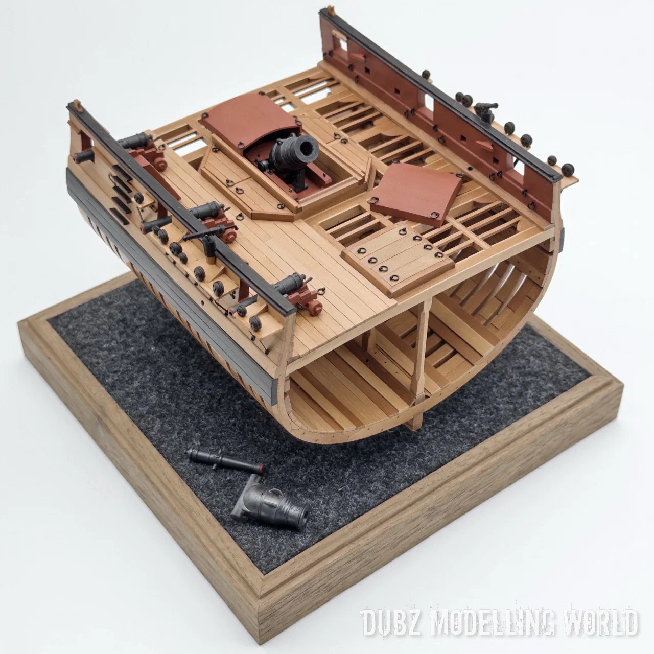
What makes her so interesting for a model is the bomb vessel layout: a heavy mortar sitting in a strongly built pit amidships, the shell room below it, and a hull structure built to absorb the enormous recoil of firing almost straight upwards. A cross-section shows all of this at once.
The kit
The model is a plank-on-frame cross-section kit in 1:72 by Miniature Arts – Shipmodel Kits, based on the original design by Jeff Staudt and the MSB forum. Finished, it measures about 123 mm in length, 120 mm in width and 90 mm in height – small, but packed with structure. I was sent the kit for a review, liked it a lot and then decided to build it.
Two warnings before you start. First, the instructions are in Chinese and completely inadequate; download the free MSB plans and study the building sequence thoroughly. Second, the laser on my kit was not well adjusted. The kerf – the width of material burned away by the laser – is around 0.2 mm, which sounds like nothing until ten planks in a row leave a gap of 2 mm. It is not a kit for beginners: you need patience, calm and the willingness to correct parts.
“Even if there are some problems with the kit – and there always are – for the price everyone should strike and build this little cross-section. The price/performance ratio is incredibly good. And I am a damn perfectionist.”
Frames, keel and jig
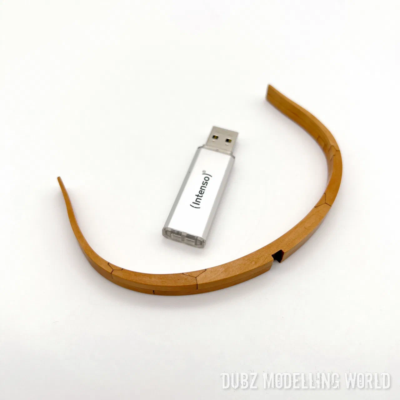
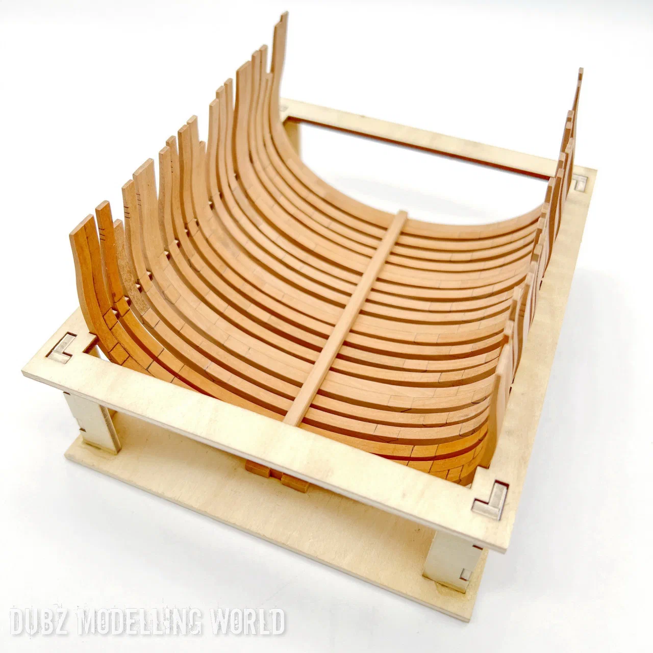
I started with a first frame, the keel and the building jig. From about frame 8 onwards the frames no longer fit into the jig, which has to be opened up – something the instructions don’t tell you. Once all frames were assembled they were cleaned and their height adjusted on the keel.
The rabbet in the keel had to wait. The large kerf meant that a lot of material had to be removed to get the correct bevels, which in turn made parts smaller and changed overall dimensions. After days of dry fitting, testing and looking ahead, I glued the frames onto the keel, centring each one carefully so that nothing wobbled in the jig. In the end the keel rabbet was never cut: I had thought I could do it later, but found no way to do so without risking damage.
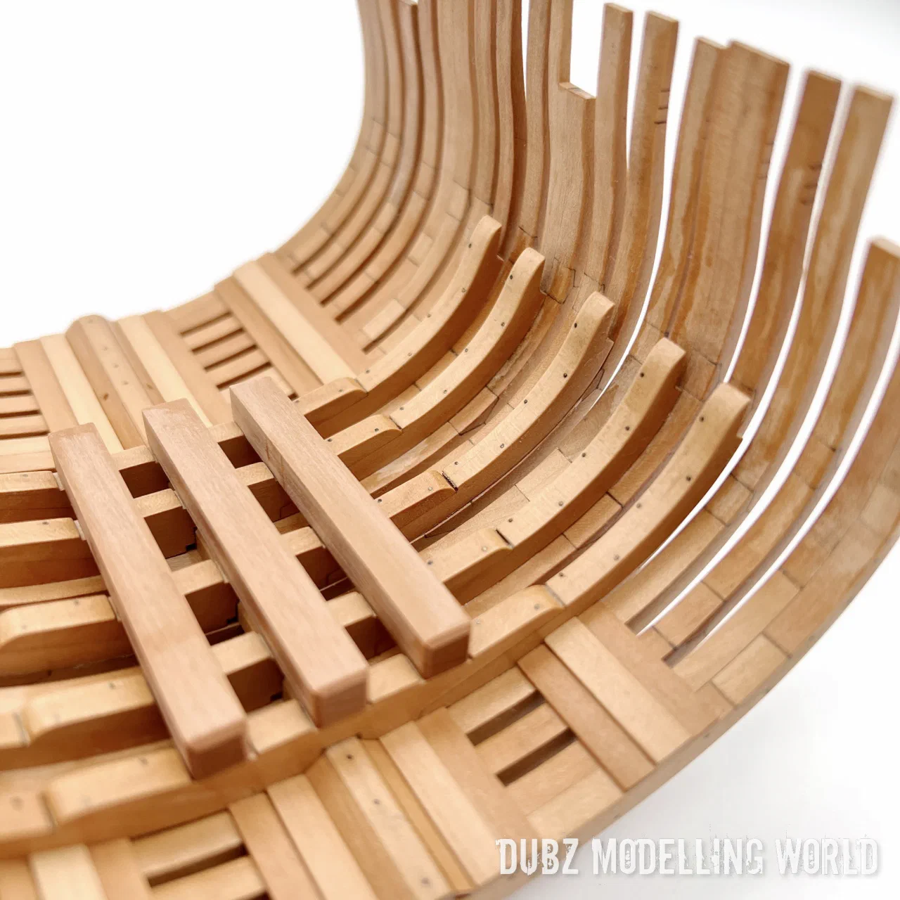
With keelson and floor riders in, the little structure became pretty stable. Then came the inner layers: limber board, limber strake, footwaling, the upper and lower footwaling strakes and the thickstuff – and lots of nails.
The shell room
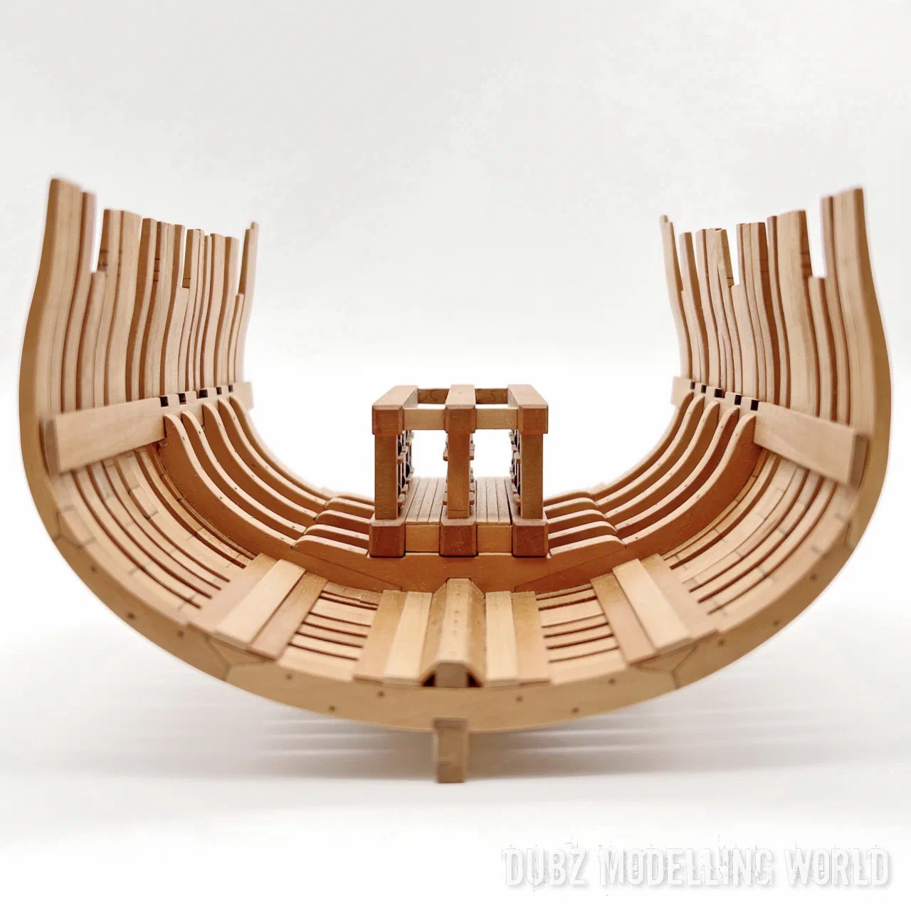
The shell room was the trickiest part of the lower hull. At this scale every angle and every tenth of a millimetre matters if the whole ensemble is to look right. I did not use the kit’s two-part upper and lower support beams: I didn’t like the construction and needed them slightly higher. Because I adjusted parts and joints from the bottom upwards, the hull may end up a little flatter than intended.
As a small modification I decided to show the walls of the shell room, and later added its doors at the front and closed the back. It is very dark in there – but it is there.
Mortar pit and upper deck
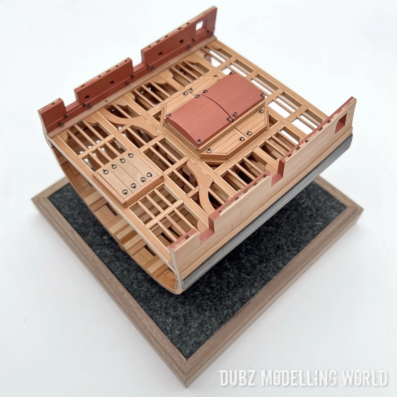
Next came the mortar pit beams and planking, dry fitted as far as possible before anything was glued. I also added fillers between the frames – something I should have done at the very beginning. It is always about learning. The outside of the frames was sanded, oiled and finished with a ball-matting technique.
The mortar pit planking is a good example of the kerf problem. The secondary planking comes as one lasered part with engraved nails, the primary planking as ten single planks – and ten times 0.2 mm adds up to a 2 mm gap. So these planks were redone.
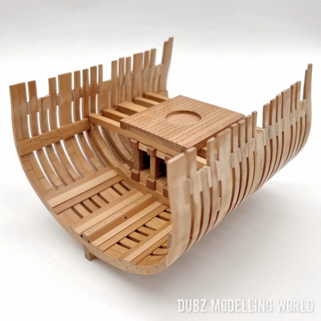
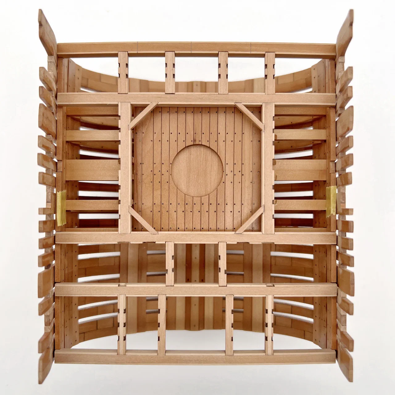
The upper deck beams, trimmer beam, angled carlings and carlings followed. Here the kit uses sandwiched beams, and I really don’t like this design – the more so as the wood colours of the layers differ strongly, which becomes even more visible once oiled. It is a typical compromise of plank-on-frame kits that need to be buildable for a broad audience. The double lodging knees were also designed too small, with no allowance for sanding to fit, and the hatch is shown wrongly in the instructions.
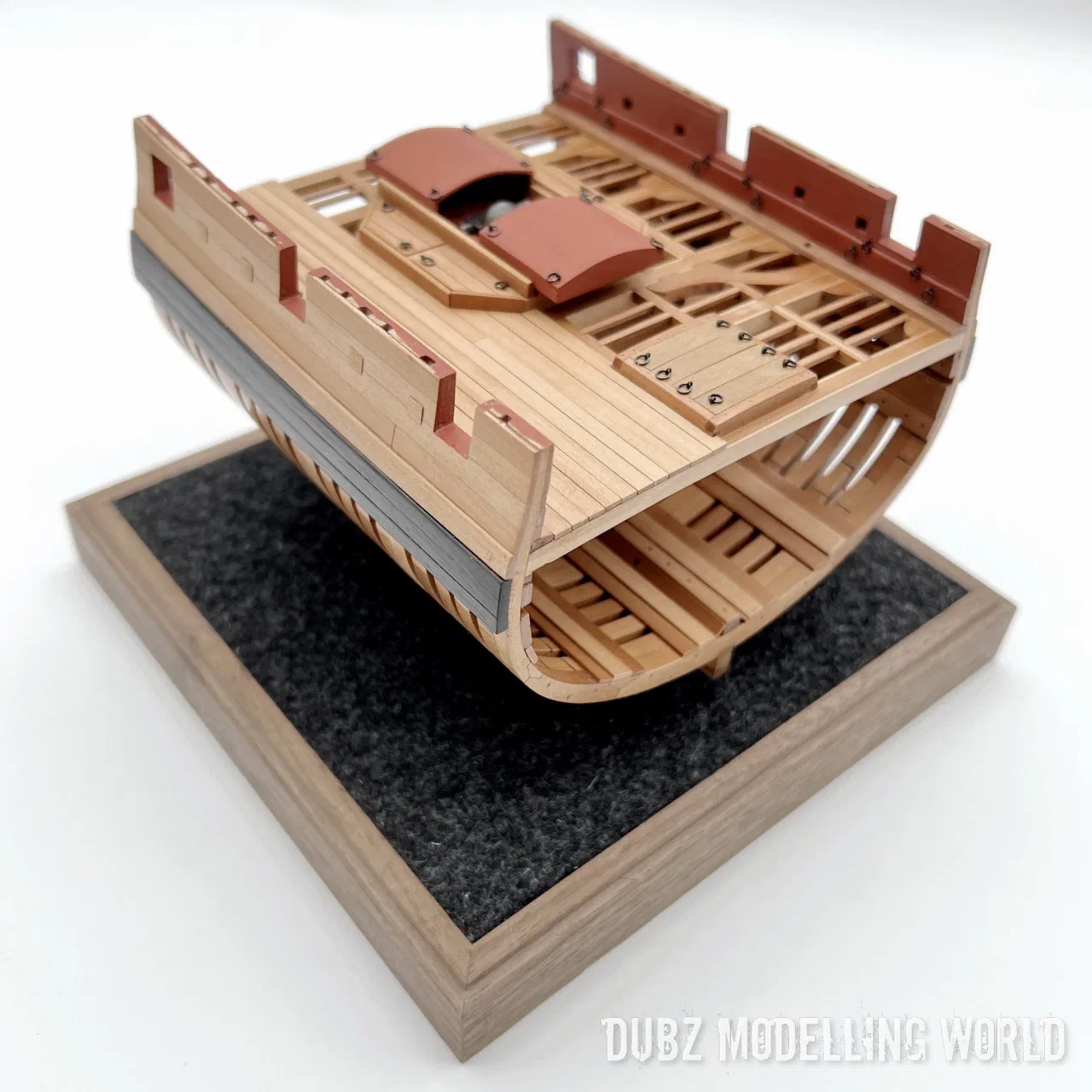
The mortar housing was built as in the kit and in the Goodwin book. Many adjustments were needed: the side covers, the canopy planks (again the kerf), the inner canopy transom. Nothing there is glued; everything stays removable.
Planking inside and out
The kit’s inboard planking is very simplified – no waterway, no spirketting. I did not like that, and built both from scratch, orientated on the drawings in the Anatomy of the Ship. It looks easy once it is done, but took a good while. One mistake I only noticed afterwards: I followed the MSB drawings for the spirketting, and it should reach up to the gunports. It sits too low – not something I can or will change at this stage.
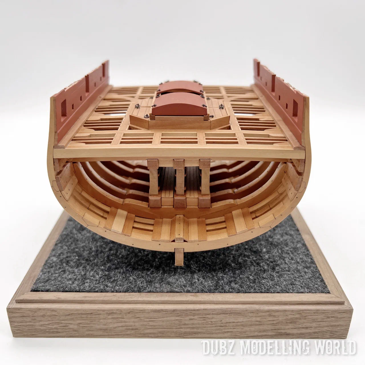
Outboard, the kit is missing the upper main wale and offers a simple plank instead. I made the upper main wale, the filling wale and the lower main wale myself; the kit wale parts were too long anyway, so the lasered nails would not have lined up. I want real nails in any case. Filling the sweep ports is a job I hate – in the end I faked the port lids with a very thin sheet of pear.
On deck I laid part of the planking, including the two binding strakes, and decided to plank the inner hull partially as well, leaving the structure visible on one side. After that the sheer rail went on. I decided against treenails.
Fittings and small details
Then came the many small parts: cleats, kevel cleats, ring bolts on deck, the scuppers and the channels. The kit’s channels are incomplete – they should run all the way to the cut – and the deadeyes are missing altogether, as they are in the MSB drawings. So I scratched the missing part of the channel.
The entry port ladder and the centreline stanchions were made with the help of small jigs. Building those jigs is one of the most satisfying parts of the hobby.
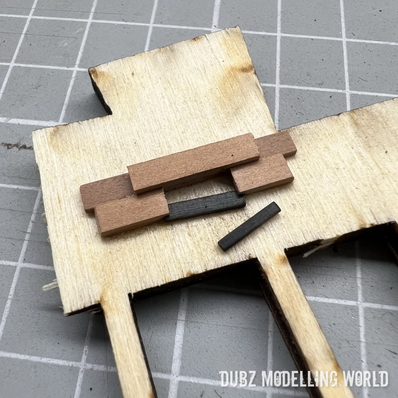
Long after the main work, Zoltan of Dry-Dock Models & Parts kindly sent me some of his new photo-etched sweep port hinges – another item ticked off the list. The chainplates and deadeyes I had avoided for quite a while: the kit includes neither, and the front part of the channel board is missing too. I used Dry-Dock deadeyes and iron chain strops and made the chainplates myself. It is not exactly as on the contemporary drawing, but it tells the story, and the side no longer looks naked.
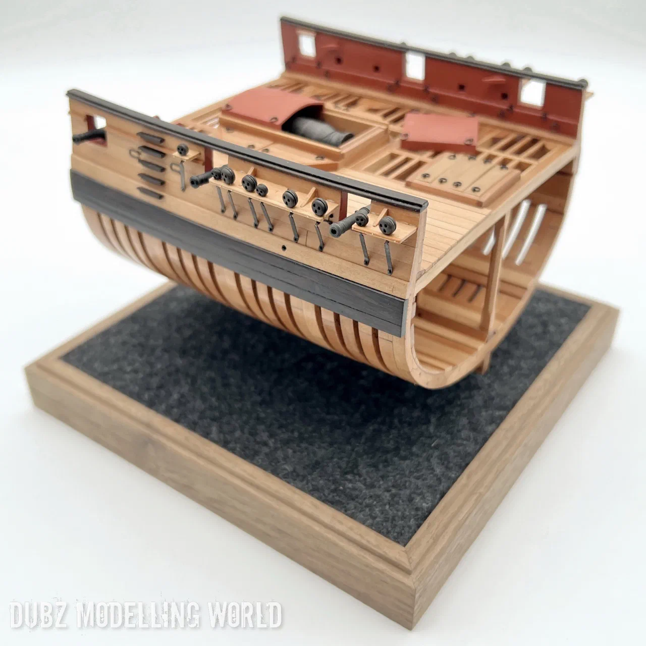
The swivel gun and its pedestal are not part of the kit either; I had some spare 3D-printed swivels from Master Korabel that fit perfectly. The kevel cleats on the sheer rail were one of the last missing details.
Guns and mortar
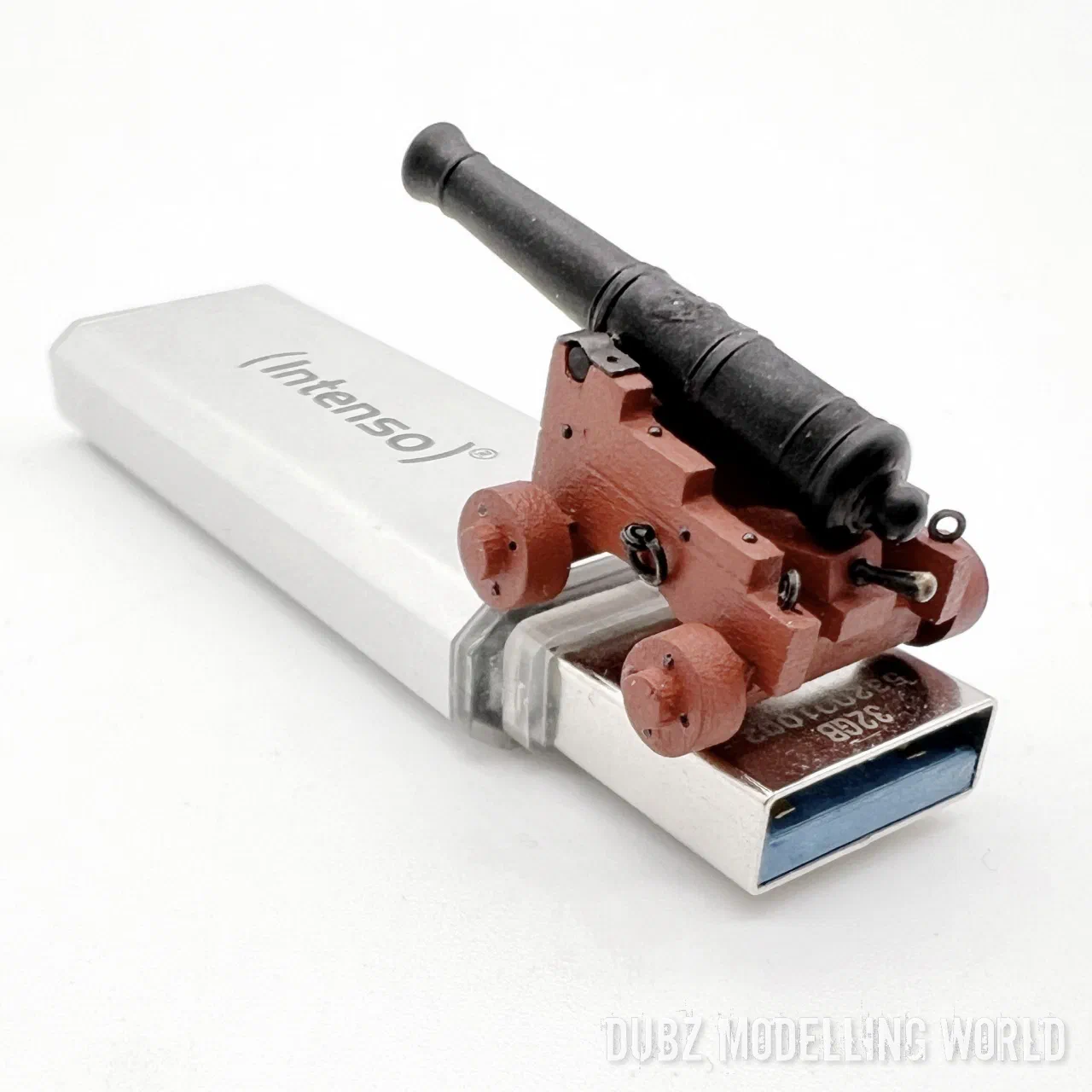
The kit’s gun barrels are too top-heavy and have the wrong shape. My first gun used a 3D-printed Russian barrel from Master Korabel; there would be no gun rigging. In the end I settled on three guns. The final barrels were printed for me by Daniel (Dafi), primed with Vallejo primer and then rubbed with a pencil to give them a slightly metallic sheen. The carriages are a little too low – but at some point a project has to be called done.
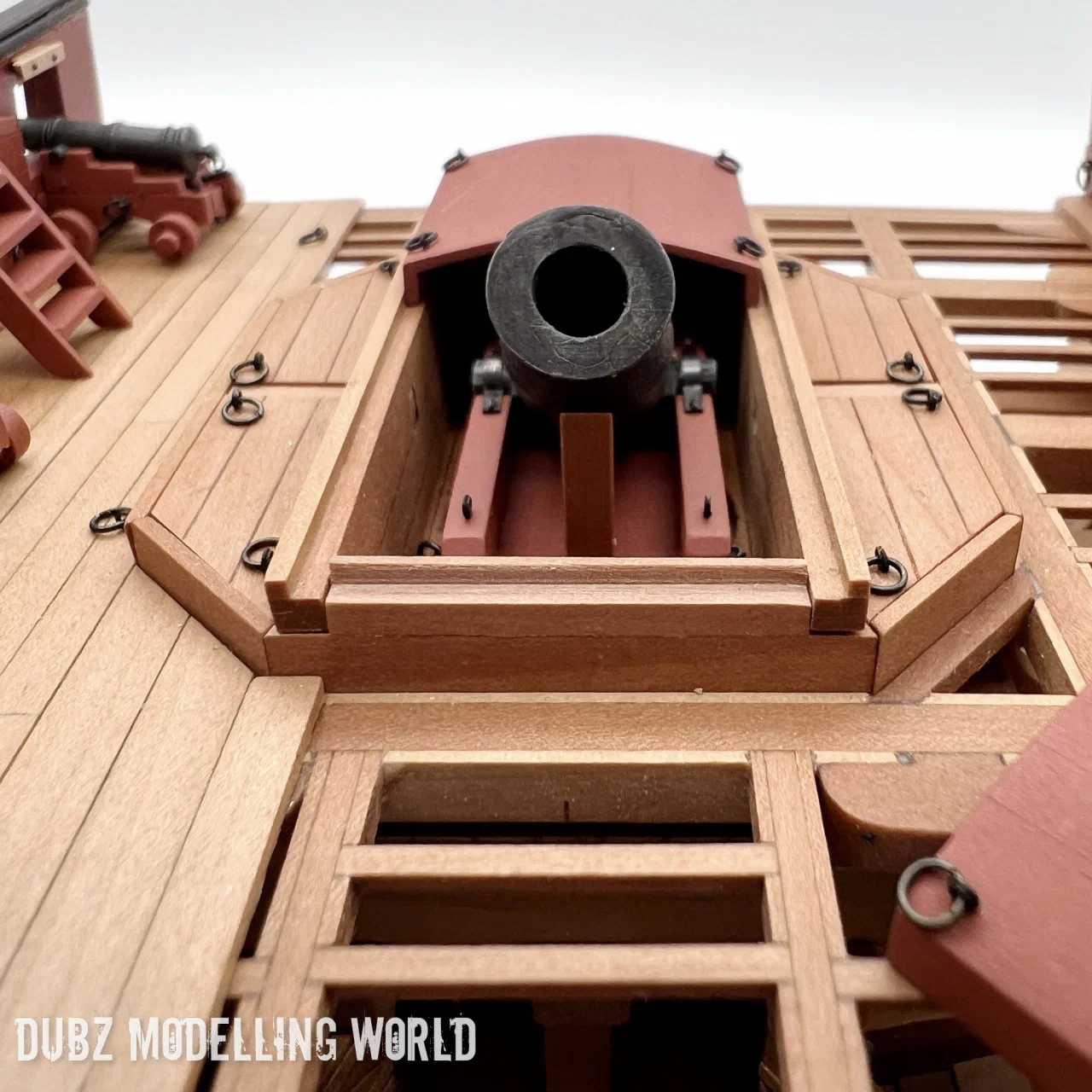
The mortar of the kit, cast in white metal, was – let’s be honest – the weakest part of the whole kit. I made the cap square and a simplified mortar support for it first. Then Daniel performed another small miracle and reconstructed and printed a correct mortar. What a difference, and what an upgrade for the model.
The finished cross-section
The base and the case were made in my usual style. Nearly two years after the first frame – with a break in between and a bout of COVID that cost me seventeen days – the Granado cross-section is finished.
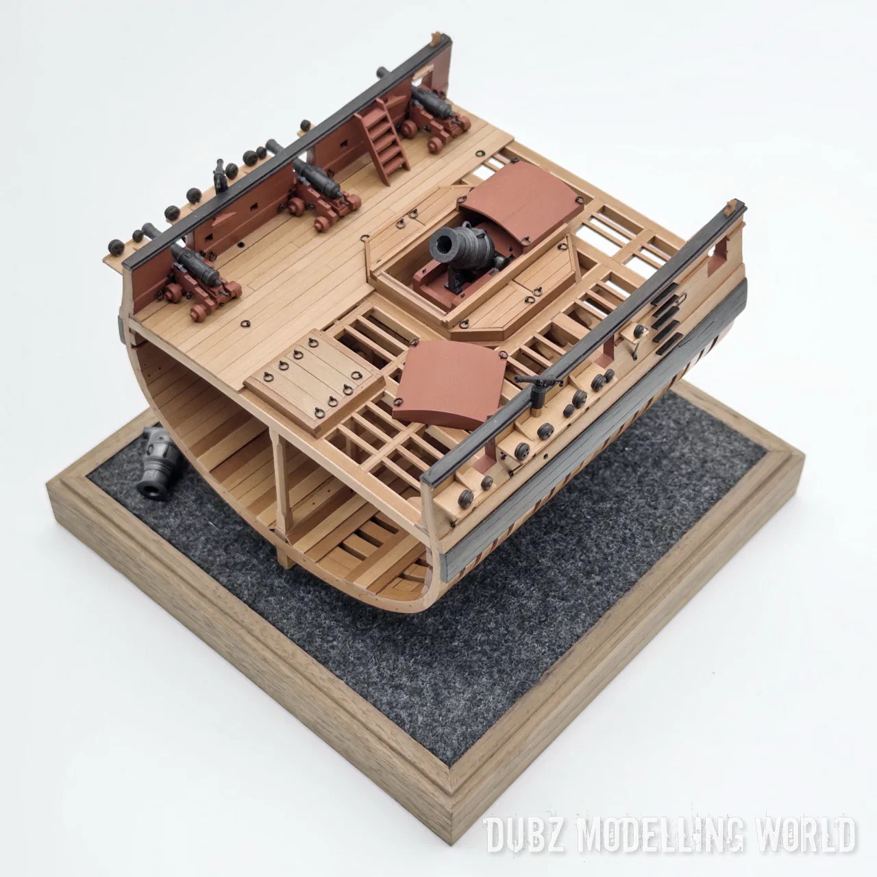
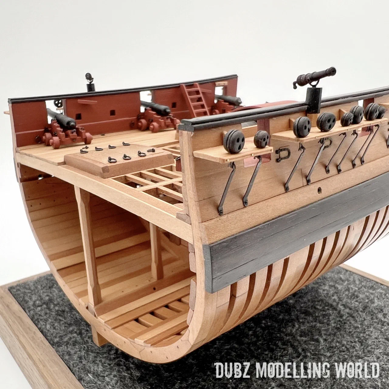
It is not perfect: the spirketting is too low, the keel rabbet is missing and the sandwiched beams still bother me. But it shows the inner life of a bomb vessel in a way a full hull never could – and for anyone interested in 18th-century ship construction, this little kit is well worth the effort.